
Introduction
1. Rf & Transmission Performance Testing
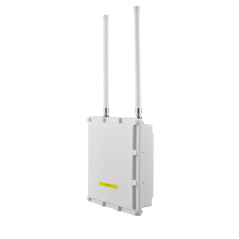
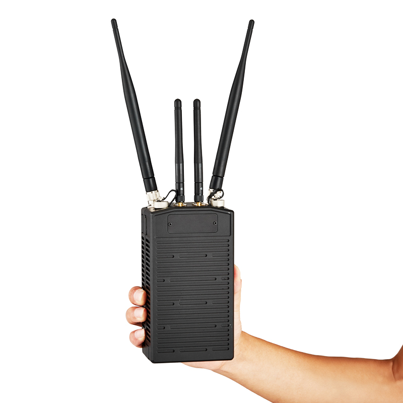
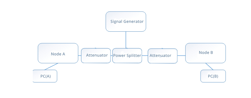
Build up a test environment according to the right figure. The test instrument is Agilent E4408B. Node A and node B are the devices under test. Their RF interfaces are connected through attenuators and connected to the test instrument via a power splitter to read data. Among them, node A is the robot communication module, and node B is the gateway communication module.

Test Environment Connection Diagram
|
Test Result |
|||
|
Number |
Detection Items |
Detection Process |
Detection Results |
|
1 |
Power indication | Indicator light turns on after powering on | Normal ☑Unnormal□ |
|
2 |
Operating Band | Log in to nodes A and B through WebUi, enter the configuration interface, set the working frequency band to 1.4GHz (1415-1540MHz), and then use the spectrum analyzer to detect the main frequency point and occupied frequency to confirm that the device supports 1.4GHz. | Normal ☑Unnormal□ |
| 3 | Bandwidth Adjustable | Log in to nodes A and B through WebUI, enter the configuration interface, set 5MHz, 10MHz, and 20MHz respectively (node A and node B keep the settings consistent), and observe whether the transmission bandwidth is consistent with the configuration through a spectrum analyzer. | Normal ☑Unnormal□ |
| 4 | Adjustable power | Log in to nodes A and B through the WebUI, enter the configuration interface, the output power can be set (set 3 values respectively), and observe whether the transmission bandwidth is consistent with the configuration through the spectrum analyzer. | Normal ☑Unnormal□ |
|
5 |
Encryption transmission | Log in to nodes A and B through the WebUI, enter the configuration interface, set the encryption method to AES128 and set the key (the settings of nodes A and B remain consistent), and it is verified that the data transmission is normal. | Normal ☑Unnormal□ |
|
6 |
Robot End Power Consumption | Record the average power consumption of the nodes on the robot side in normal transmission mode through a power analyzer. | Average power consumption: < 15w |
2. Data Rate and Delay Test

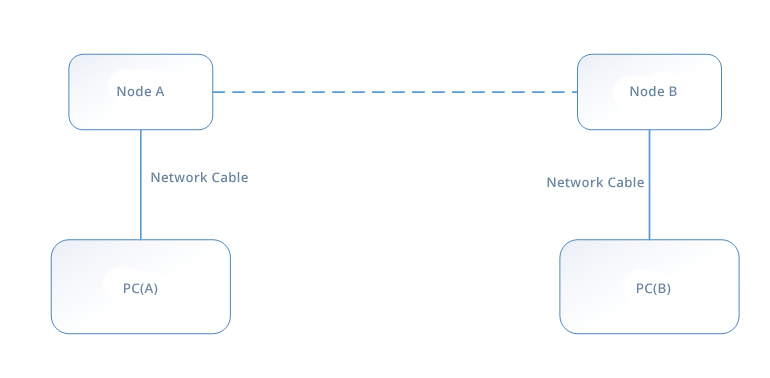
Test method: Nodes A and B (node A is a handheld terminal and node B is a wireless transmission gateway) select appropriate center frequencies at 1.4GHz and 1.5GHz respectively to avoid interference frequency bands in the environment, and configure a max 20MHz bandwidth. Nodes A and B are connected to PC(A) and PC(B) through network ports respectively. The IP address of PC(A) is 192.168.1.1. The IP address of PC(B) is 192.168.1.2. Install iperf speed testing software on both PCs and perform the following test steps:
●Execute the command iperf-s on PC (A)
●Execute the command iperf -c 192.168.1.1 -P 2 on PC (B)
●According to the above test method, record the test results of 20 times and calculate the average value.
| Test Results | |||||
| Number | Preset Test Conditions | Test Results(Mbps) | Number | Preset Test Conditions | Test Results (Mbps) |
| 1 | 1450MHz@20MHz | 88.92 | 11 | 1510MHz@20MHz | 88.92 |
| 2 | 1450MHz@20MHz | 90.11 | 12 | 1510MHz@20MHz | 87.93 |
| 3 | 1450MHz@20MHz | 88.80 | 13 | 1510MHz@20MHz | 86.89 |
| 4 | 1450MHz@20MHz | 89.88 | 14 | 1510MHz@20MHz | 88.32 |
| 5 | 1450MHz@20MHz | 88.76 | 15 | 1510MHz@20MHz | 86.53 |
| 6 | 1450MHz@20MHz | 88.19 | 16 | 1510MHz@20MHz | 87.25 |
| 7 | 1450MHz@20MHz | 90.10 | 17 | 1510MHz@20MHz | 89.58 |
| 8 | 1450MHz@20MHz | 89.99 | 18 | 1510MHz@20MHz | 78.23 |
| 9 | 1450MHz@20MHz | 88.19 | 19 | 1510MHz@20MHz | 76.86 |
| 10 | 1450MHz@20MHz | 89.58 | 20 | 1510MHz@20MHz | 86.42 |
| Average Wireless Transmission Rate: 88.47 Mbps | |||||
3. Latency Test
Test method: On nodes A and B (node A is a handheld terminal and node B is a wireless transmission gateway), select appropriate center frequencies at 1.4GHz and 1.5GHz respectively to avoid environmental wireless interference bands, and configure a 20MHz bandwidth. Nodes A and B are connected to PC(A) and PC(B) through network ports respectively. The IP address of PC(A) is 192.168.1.1, and the IP address of PC(B) is 192.168.1.2. Perform the following test steps:
●Run the command ping 192.168.1.2 -I 60000 on PC (A) to test the wireless transmission delay from A to B.
●Run the command ping 192.168.1.1 -I 60000 on PC (B) to test the wireless transmission delay from B to A.
●According to the above test method, record the test results of 20 times and calculate the average value.
| Test Result | |||||||
| Number | Preset Test Conditions | PC(A) to B Latency (ms) | PC(B) to A Latency (ms) | Number | Preset Test Conditions | PC(A) to B Latency (ms) | PC(B) to A Latency (ms) |
| 1 | 1450MHz@20MHz | 30 | 29 | 11 | 1510MHz@20MHz | 28 | 26 |
| 2 | 1450MHz@20MHz | 31 | 33 | 12 | 1510MHz@20MHz | 33 | 42 |
| 3 | 1450MHz@20MHz | 31 | 27 | 13 | 1510MHz@20MHz | 30 | 36 |
| 4 | 1450MHz@20MHz | 38 | 31 | 14 | 1510MHz@20MHz | 28 | 38 |
| 5 | 1450MHz@20MHz | 28 | 30 | 15 | 1510MHz@20MHz | 35 | 33 |
| 6 | 1450MHz@20MHz | 28 | 26 | 16 | 1510MHz@20MHz | 60 | 48 |
| 7 | 1450MHz@20MHz | 38 | 31 | 17 | 1510MHz@20MHz | 46 | 51 |
| 8 | 1450MHz@20MHz | 33 | 35 | 18 | 1510MHz@20MHz | 29 | 36 |
| 9 | 1450MHz@20MHz | 29 | 28 | 19 | 1510MHz@20MHz | 29 | 43 |
| 10 | 1450MHz@20MHz | 32 | 36 | 20 | 1510MHz@20MHz | 41 | 50 |
| Average wireless transmission delay: 34.65 ms | |||||||
4. Anti-jamming Test
Set up a test environment according to the above figure, in which node A is the wireless transmission gateway and B is the robot wireless transmission node. Configure nodes A and B to 5MHz bandwidth.
After A and B establish a normal link. Check the current working frequency through the WEB UI DPRP command. Use the signal generator to generate a 1MHz bandwidth interference signal at this frequency point. Gradually increase the signal strength and query the changes in the working frequency in real time.
| Sequence Number | Detection Items | Detection Process | Detection Results |
| 1 | Anti-jamming capability | When strong interference is simulated through the signal generator, nodes A and B will automatically execute the frequency hopping mechanism. Through the WEB UI DPRP command, you can check that the working frequency point has automatically switched from 1465MHz to 1480MHz | Normal ☑Unnormal□ |
Post time: Mar-22-2024