

Introduction
Base on the Hangzhou ** Intelligent Technology Company select the wireless ad hoc network radio to use for the robot dog test report.

User
Hangzhou ** Intelligent Technology Company

Market Segment
Robot Dog and UGV


1、Test Background
1.1 Test location
Hangzhou ** Intelligent Technology Company
1.2 Testing time
2023.10.23
1.3 Testing Purposes
The purpose of this test is mainly to test the wireless transmission effect of three wireless ad hoc network radio stations, including IWAVE’S Communications, Chengdu ** company, and Beijing**company, under LOS(Line-of-sight) conditions and NLOS (none-line-of-sight) conditions, to simulate and test the actual application scenarios between the Robot dog and the operator.
1.4 Test scenario selection
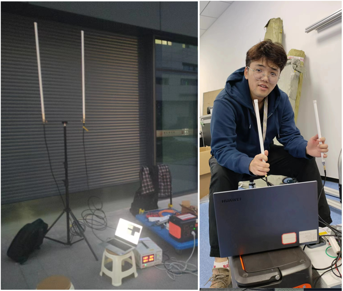
According to the actual scenario, set the antenna height of the receiving end to 1.5 meters and the height of the Robot dog end to 0.5-0.6 meters. Use the packet filling tool at the transmitting end (simulated Robot dog end) to inject packets into the laptop computer at the receiving end (simulated controller end).
The test scenarios include outdoor scenes and indoor scenes.
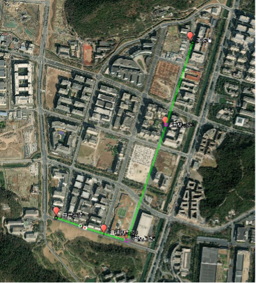
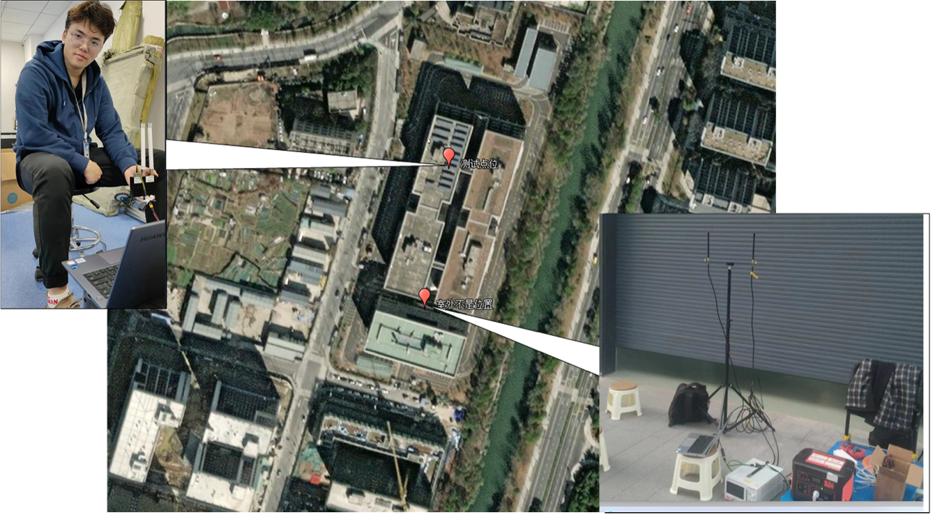
The outdoor scene also includes a 0.5 km line-of-sight test point, a 1.1 km line-of-sight test point, a 1.15 km non-line-of-sight test point (large corner), a 1.2 km non-line-of-sight test point (where the road ends after turning).
For the indoor scene, two locations with relatively serious obstructions were selected: the entrance to the stairway and the warehouse.
|
NO. |
Testing scenarios |
Test point |
Remark |
|
1 |
Outdoor scene test |
Point 1: 0.5 km LOS test point | |
|
2 |
Point 2: 1.1 km LOS test point | ||
|
3 |
Point 3: 1.15 km non-line-of-sight test point | ||
|
4 |
Point 4: 1.2 km non-line-of-sight test point | ||
|
5 |
Indoor scene test |
Point 1: Safety passage stairway | |
|
6 |
Point 2: Warehouse |
2、Test Scenarios ---Outdoor Scene
2. Outdoor Scene Test
2.1 Test Method Description
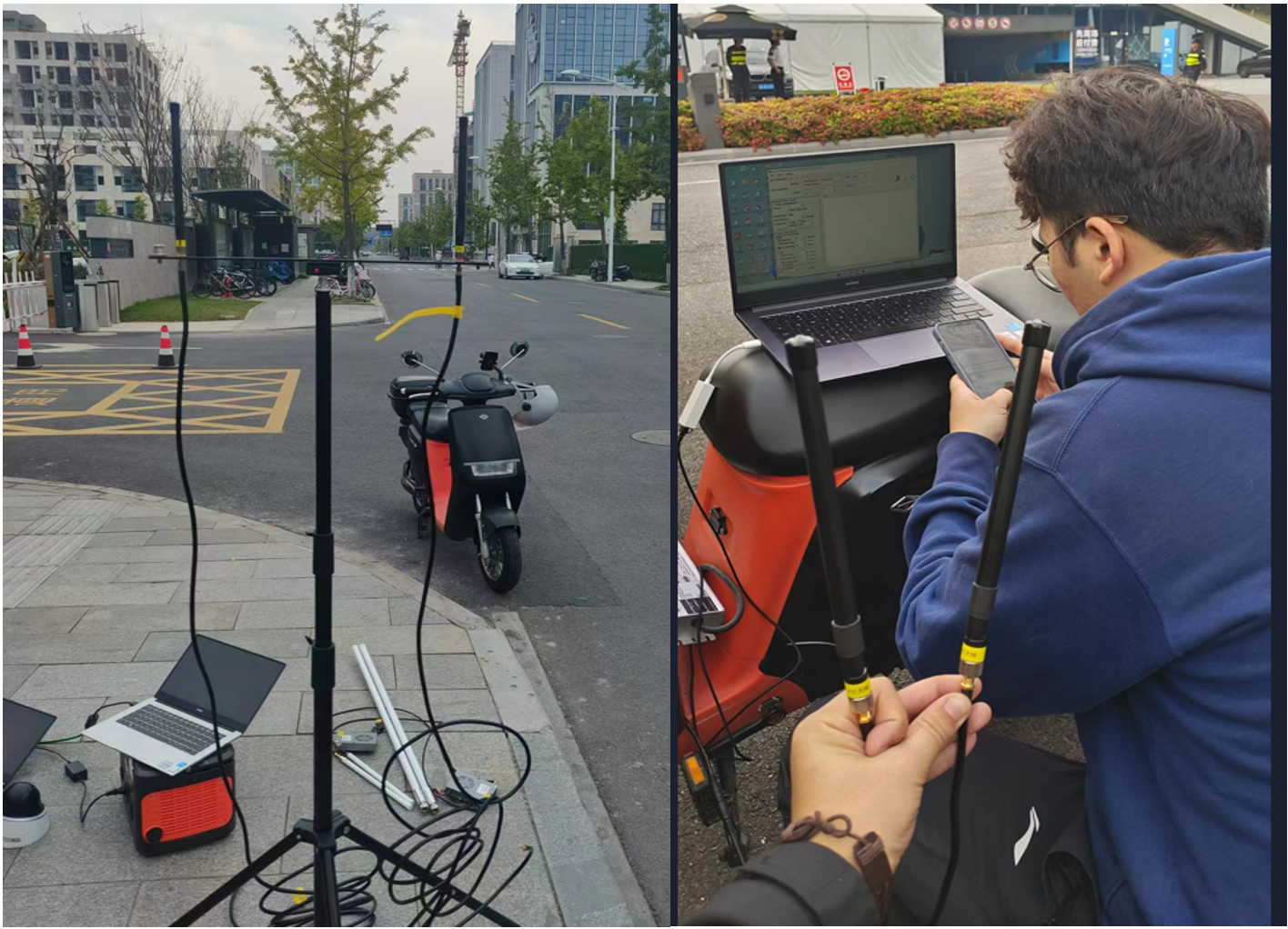
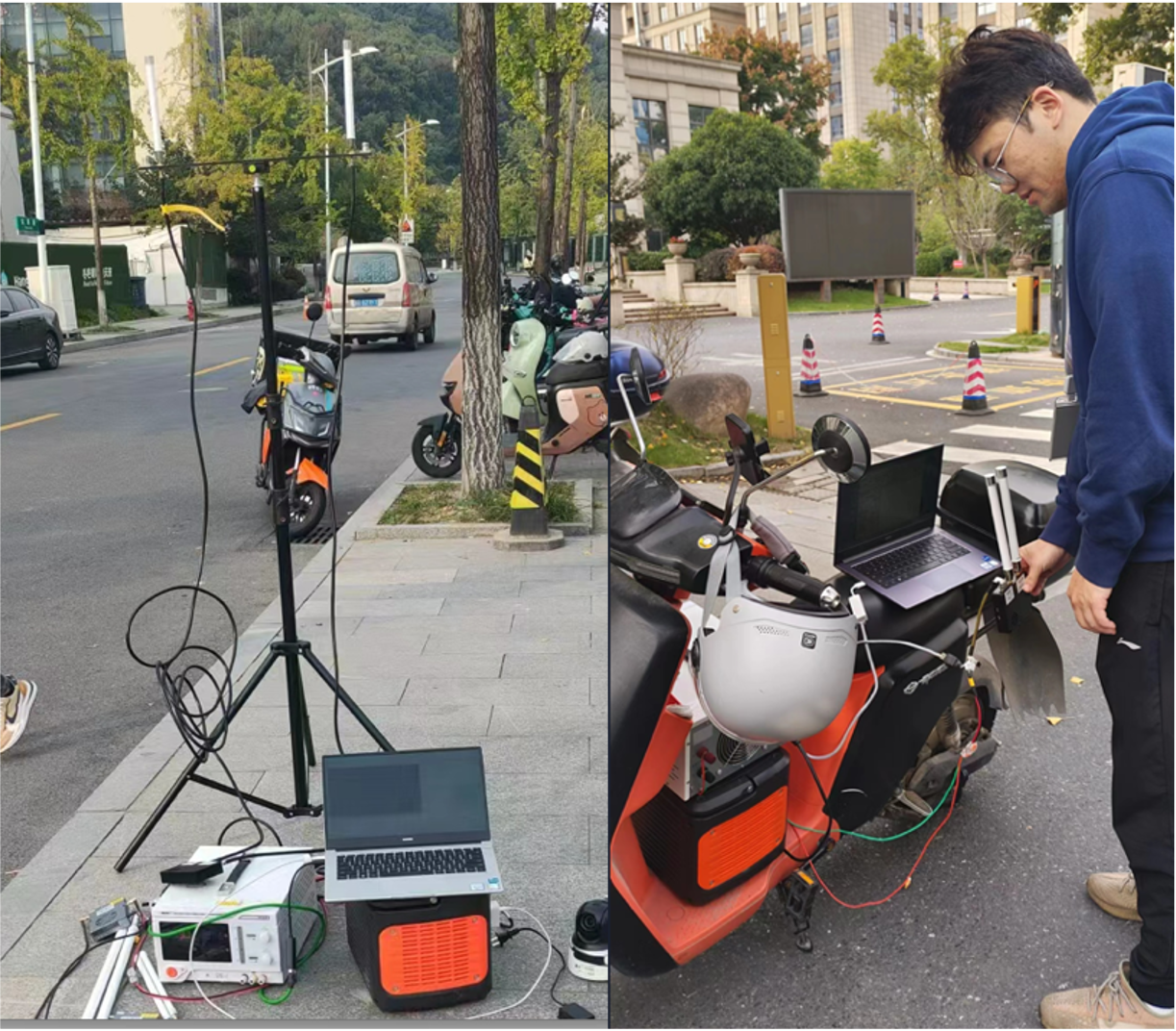
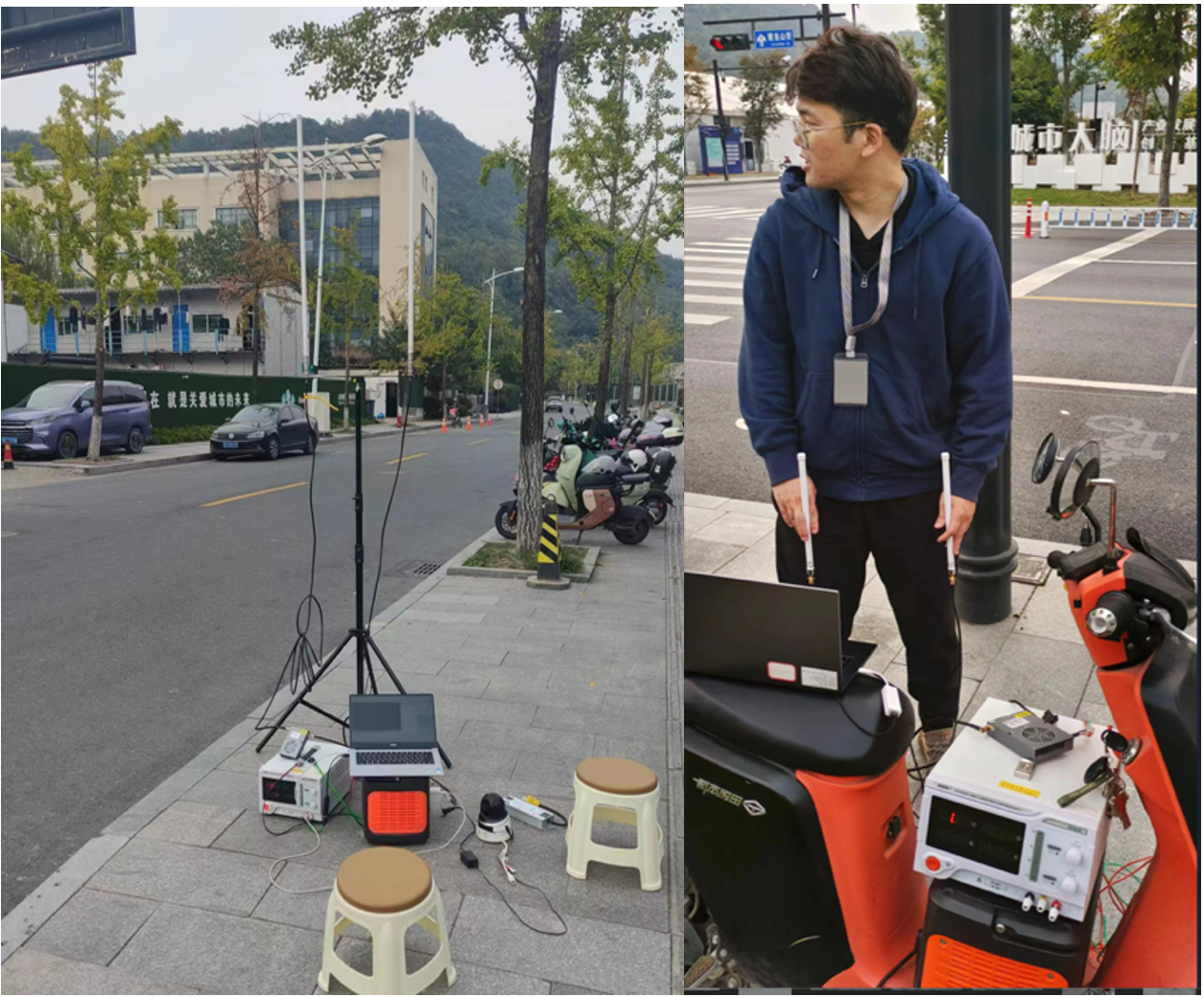
The test scene was chosen to be on the road directly in front of the park where Hangzhou ** Intelligent Technology Company is located. The receiving end (simulated controller end) antenna was set up at a height of about 1.5meter, and two engineers rode electric bicycles to simulate the transmitter end (simulated Robot dog end).) , the actual height of the transmitter is about 0.5 meter; see the figure below:
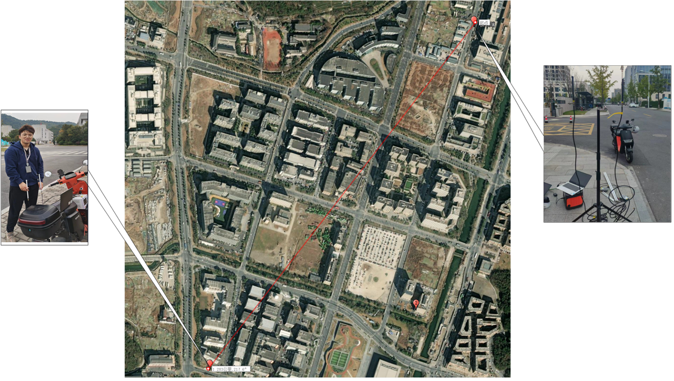
The receiving end uses a wireless ad hoc network radio + a laptop and runs the IPerf software to collect traffic statistics. The transmitter uses a wireless ad hoc network radio + a laptop and runs the IPerf software to fill packets at different rates. Test the average transmission bandwidth of four location points respectively ;
Manufacturer equipment information:
|
NO. |
Company |
Frequency (MHz) |
Power (W) |
Antenna gain (dbi) |
Remark |
|
1 |
IWAVE Communications |
806-826 MHz |
2 |
2 |
|
|
2 |
Chengdu**company |
1427-1447Mhz |
10 |
4/5 |
|
|
3 |
Beijing***company |
566-606 MHz |
2 |
6 |
|
3、Three Comapny's Progress and Result
3.1 IWAVE Communication Test Process and Result
Test on-site environment setup:
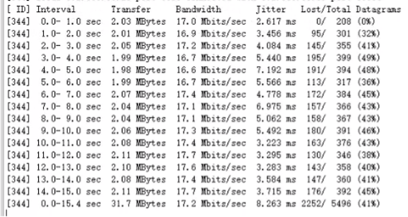
Ø Data packet filling situation at point 1: the maximum packet filling rate is 17.2Mbps
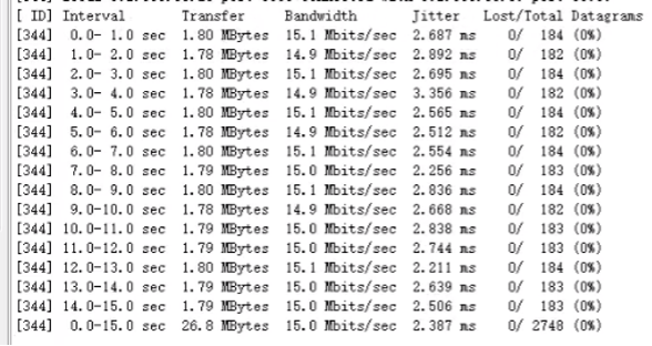
Ø Point 2 data packet filling situation: the maximum packet filling rate is 15.0Mbps
Ø Data packet filling situation at point 3 : the maximum packet filling rate is 10.9 Mbps
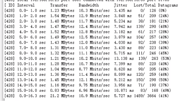
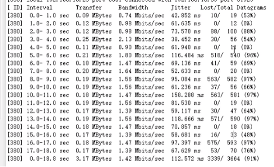
Ø Point 4 data packet filling situation: the maximum packet filling rate is 1.42Mbps
3.2 Chengdu** company Test Progress and Result
Test on-site environment setup:
Ø Data packet filling situation at point 1: the maximum packet filling rate is 43.2Mbps.

Ø Point 2 data packet filling situation: the maximum packet filling rate is 14.4Mbps.

Ø Data packet filling situation at point 3: the maximum packet filling rate is 2.51Mbps and 2.01Mbps;

Ø Data packet filling situation at point 4: The wireless is interrupted and the packet sending and receiving test cannot be carried out;


3.3 Beijing *** company Test Process and Result
Test on-site environment setup:
Ø Data packet filling situation at point 1: the maximum packet filling rate is 44.9Mbps.

Ø Point 2 data packet filling situation: the maximum packet filling rate is 10.9Mbps.

Ø Data packet filling situation at point 3: the maximum packet filling rate is 6.6Mbps;

Ø Point 4 data packet filling situation: wireless interruption, packet sending and receiving test cannot be carried out.

4、Test Scenarios ---Indoor Scene
4 Indoor Scene Test
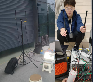
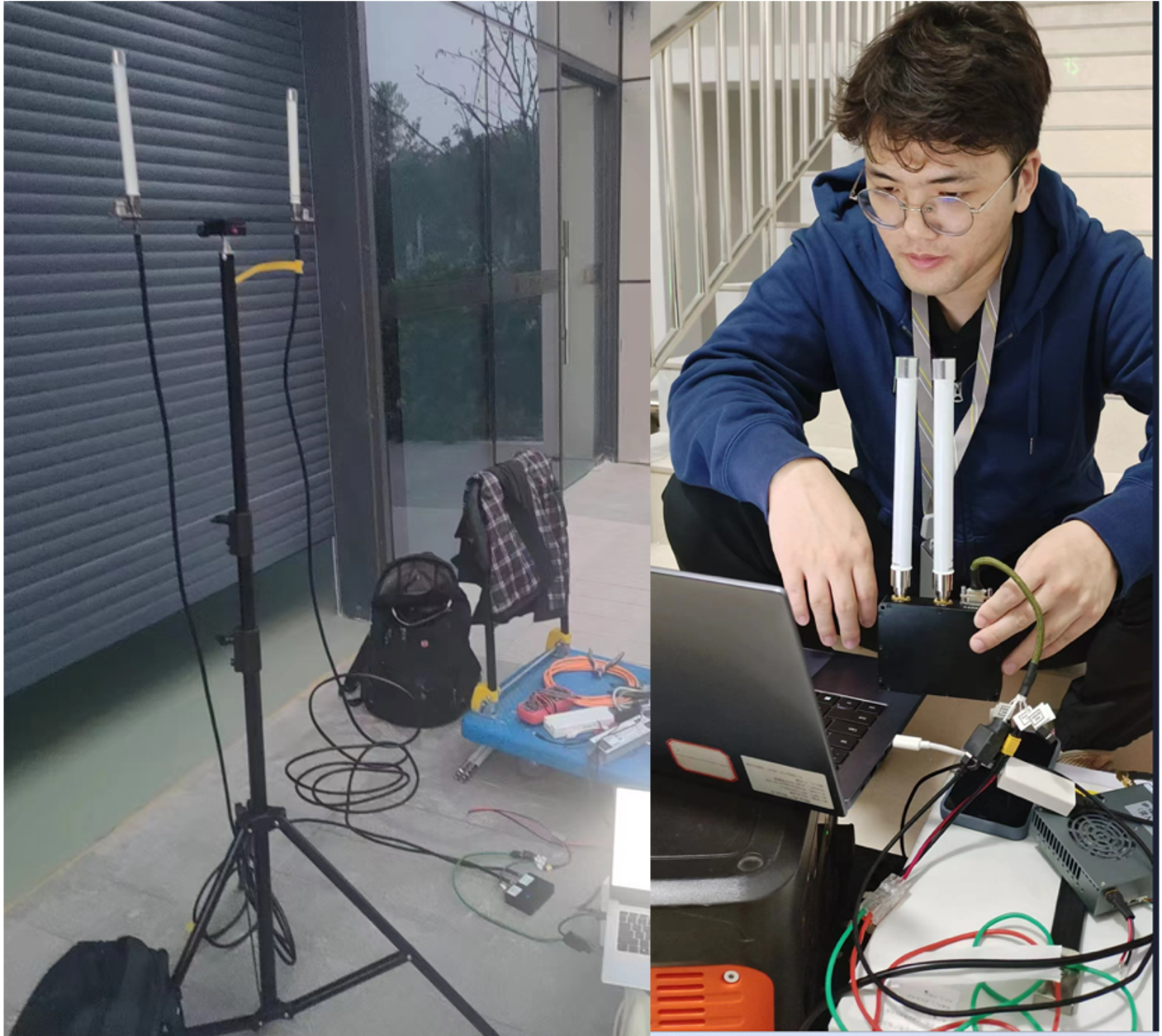
4.1 Test Environment Description
When testing in a building, a corner outside the Hangzhou**Intelligent Technology Company building was chosen to set up the receiver. Then choose the stairwell (Point 1) and the warehouse (Point 2) with serious indoor occlusion as the contracting test location; the three antennas are set up at the same height to simulate the actual application scenario (simulated controller end 1.5km high, simulated Robot dog end 0.5meter high), record the packet sending and receiving status.
5、Three Comapny's Progress and Result
5.1 IWAVE Communication Test Process and Result
Test on-site environment setup:
Ø Data packet filling situation at point 1: the maximum packet filling rate is 15.2Mbps;

Ø at point 2: During the warehouse test, the maximum packet filling rate is 14.7 Mbps ;

5.2 Chengdu** Company Test Process and Result
Test on-site environment setup:
Ø Data packet filling situation at point 1: the maximum packet filling rate is 6.15Mbps.

Ø Point 2 data packet filling situation: the maximum packet filling rate is 23.4Mbps.

5.3 Beijing *** company Test Process and Result
Test on-site environment setup:
Ø Data packet filling situation at point 1: the maximum packet filling rate is 24.8Mbps.

Ø Point 2 data packet filling situation: the maximum packet filling rate is 23.3Mbps.

Summary
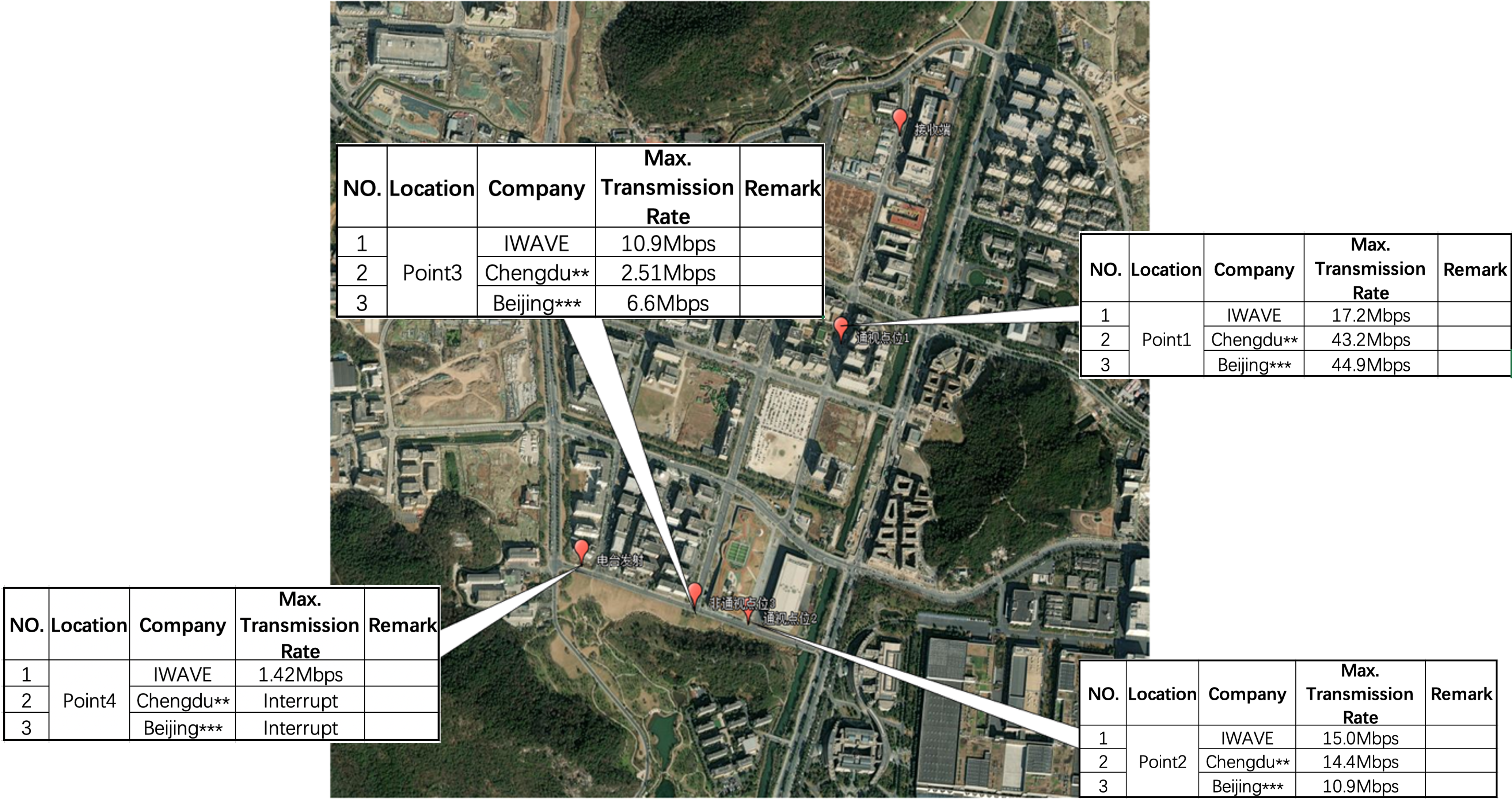
In the outdoor test scenario, at point 1 and point 2, all three company’s radios can meet the transmission rate requirement of 6 Mbps or above. At point 3, IWAVE Communications and Beijing **Company can meet the 6 Mbps transmission rate requirement. At point 4, only IWAVE Communications can keep the connection normal and can carry out 1.5Mbps data upstream traffic. In long-distance and non-line-of-sight situations, IWAVE communication equipment has better connection stability and transmission effects.
In the indoor test scenario, due to limited conditions, it was impossible to simulate more complex scenarios, and the ultimate performance of the three devices was not measured. Judging from the test results, the test results in the Hangzhou **Intelligent Technology Company building showed that all three company’s radios can meet the transmission rate requirement of above 6 Mbps.
Post time: Nov-17-2023


