
1.What is Antenna?
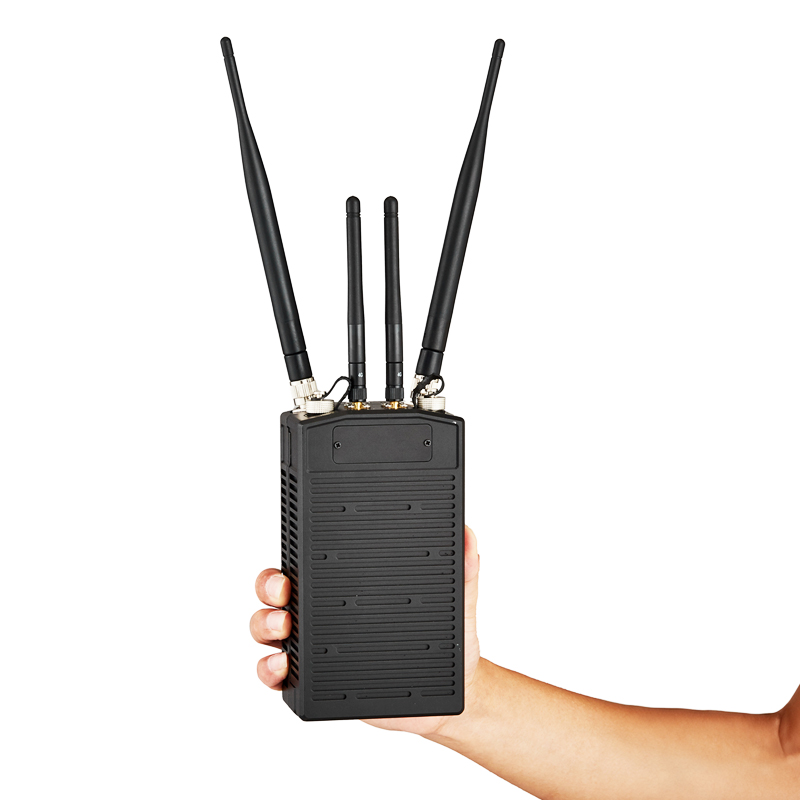
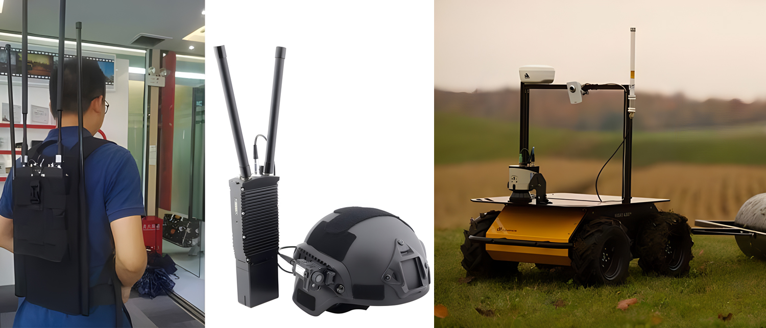
As we all know, there are all kinds of wireless communication devices in our lives, such as drone video downlink, wireless link for robot, digital mesh system and these radio transmission system use radio waves to wireless transmit information such as video, voice and data. An antenna is a device used for radiating and receiving radio waves.
2.Antenna bandwidth
When the operating frequency of the antenna changes, the degree of change of the relevant electrical parameters of the antenna is within the allowable range. The allowable frequency range at this time is the antenna frequency band width, usually referred to as bandwidth. Any antenna has a certain operating bandwidth, and it has no corresponding effect outside this frequency band.
Absolute bandwidth: ABW=fmax - fmin
Relative bandwidth: FBW=(fmax - fmin)/f0×100%
f0=1/2(fmax + fmin) is the center frequency
When the antenna works at the center frequency, the standing wave ratio is the smallest and the efficiency is the highest.
Therefore, the formula of relative bandwidth is usually expressed as: FBW=2(fmax- fmin)/(fmax+ fmin)
Because the antenna bandwidth is the operating frequency range where one or some of the electrical performance parameters of the antenna meet the requirements, different electrical parameters can be used to measure the frequency band width. For example, the frequency band width corresponding to the 3dB lobe width (the lobe width refers to the angle between two points where the radiation intensity decreases by 3dB, that is, the power density decreases by half, on both sides of the maximum radiation direction of the main lobe), and the frequency band width where the standing wave ratio meets certain requirements. Among them, the most commonly used is the bandwidth measured by the standing wave ratio.
3.The relationship between operating frequency and antenna size
In the same medium, the propagation speed of electromagnetic waves is certain (equal to the speed of light in a vacuum, recorded as c≈3×10⁸m/s). According to c=λf, it can be seen that the wavelength is inversely proportional to the frequency, and the two are the only corresponding relationship.
The length of the antenna is directly proportional to the wavelength and inversely proportional to the frequency. That is, the higher the frequency, the shorter the wavelength, and the shorter the antenna can be made. Of course, the length of the antenna is usually not equal to one wavelength, but is often 1/4 wavelength or 1/2 wavelength (generally the wavelength corresponding to the central operating frequency is used). Because when the length of a conductor is an integer multiple of 1/4 wavelength, the conductor exhibits resonance characteristics at the frequency of that wavelength. When the conductor length is 1/4 wavelength, it has series resonance characteristics, and when the conductor length is 1/2 wavelength, it has parallel resonance characteristics. In this resonance state, the antenna radiates strongly and the transmission and reception conversion efficiency is high. Although the radiation of the oscillator exceeds 1/2 of the wavelength, the radiation will continue to be enhanced, but the anti-phase radiation of the excess portion will produce a cancellation effect, so the overall radiation effect is compromised. Therefore, common antennas use the oscillator length unit of 1/4 wavelength or 1/2 wavelength. Among them, the 1/4-wavelength antenna mainly uses the earth as a mirror instead of the half-wave antenna.
1/4 wavelength antenna can achieve ideal standing wave ratio and usage effect by adjusting the array, and at the same time, it can save installation space. However, antennas of this length usually have low gain and cannot meet the needs of certain high-gain transmission scenarios. In this case, 1/2-wavelength antennas are usually used.
In addition, it has been proved in theory and practice that the 5/8 wavelength array (this length is close to 1/2 wavelength but has stronger radiation than 1/2 wavelength) or the 5/8 wavelength loading shortening array (there is a loading coil at half the wavelength distance from the top of the antenna) can also be designed or selected to get a cost-effective and higher gain antenna.
It can be seen that when we know the operating frequency of the antenna, we can calculate the corresponding wavelength, and then combined with the transmission line theory, installation space conditions and transmission gain requirements, we can roughly know the suitable length of the required antenna.
Post time: Oct-13-2023